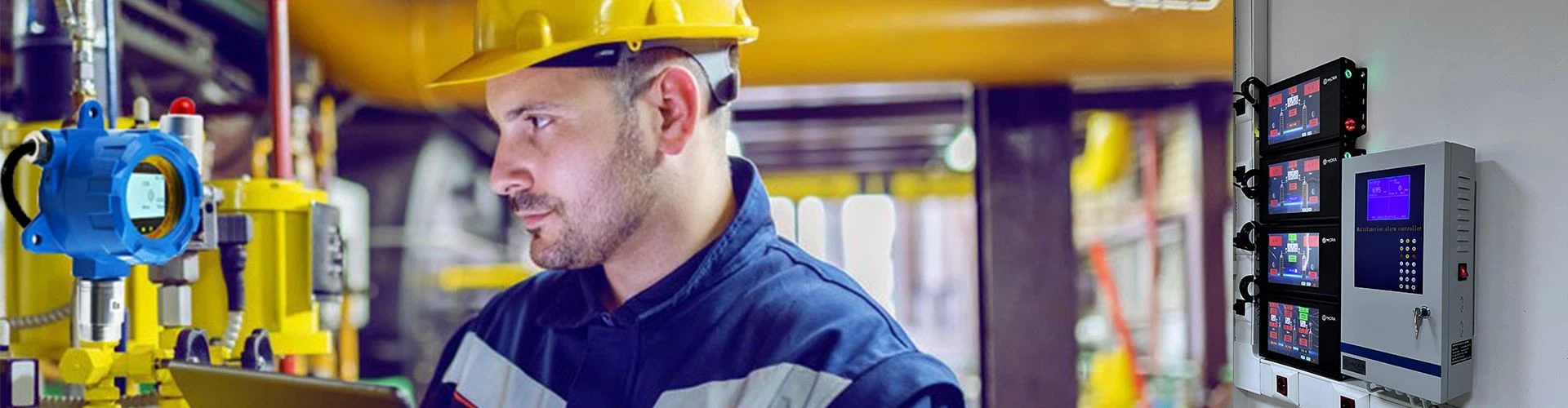


For LPG gas leakage detection and alert system, a Fixed lpg combustible gas detector and control panel is a must.
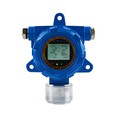
1.What is the requests for a lpg detector?
(1).High Precision and Rapid Response:
It must be able to accurately detect specific types of combustible gases (such as natural gas, liquefied petroleum gas, etc.), with the measurement unit typically being LEL% (lower explosive limit percentage).
(2).The response time (T90) must be short, typically within 30 seconds, ensuring rapid leak detection.
(3).Dual-Level Concentration Alarm Function:
Low Alarm Value (Level 1 Alarm): Typically set at 15%-25% LEL. When the concentration reaches this threshold, an audible and visual alarm is triggered, alerting personnel to check and handle the situation, but the gas supply will not be immediately shut off.
High Alarm Value (Level 2 Alarm): Typically set at 50% LEL. When the concentration reaches this dangerous threshold, the system determines it as a serious leak and immediately activates the linkage control, shutting off the main gas valve.
(4).On-Site Audible and Visual Alarm on lpg detector:
The detector itself should be equipped with a high-brightness LED indicator and a high-decibel buzzer to effectively alert on-site personnel when an alarm is triggered.
(5).Sensor Type and Lifespan of lpg sensor:
Commercial environments typically use catalytic combustion or infrared sensors. Infrared sensors have a longer lifespan, better resistance to poisoning, and are more suitable for complex environments.Sensors should have clear lifespan indication and expiration reminder functions.
(6).Calibration and Maintenance for lpg detector:
One-button calibration function is required for convenient periodic calibration using standard gases to ensure measurement accuracy.
(7).Self-diagnostic function for sensor faults is required, and fault signals should be uploaded to the control cabinet.
(8).Explosion-proof and Protection Rating:
Depending on the installation area, products with appropriate explosion-proof certification (e.g., Ex d IIB T6 Gb) must be selected.
The protection rating should be at least IP65 to prevent dust and water mist intrusion.
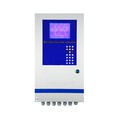
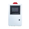
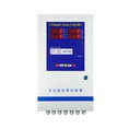
2. Functional Requirements of the Gas Alarm Control panel
(1).A large-screen LCD display should show the gas concentration values, alarm status, fault information, and operating status of all connected detectors in real time.
Each channel should have an independent indicator light clearly indicating normal, alarm, or fault status.
(2).Dual-level alarm control output:
Equipped with independent relay output contacts, corresponding to low-alarm and high-alarm levels respectively. The high-alarm relay is directly used for linkage control of the emergency shut-off solenoid valve.
(3).Linkage control logic:
This is the core function. When any lpg gas detector reaches the high-alarm concentration, the control cabinet should immediately output a passive dry contact signal to drive the solenoid valve to cut off the gas supply.
The linkage logic should be configurable, such as "any trigger" or "operation only when multiple zones are triggered simultaneously." "Any trigger" is typically used to ensure safety.
(4).Manual/automatic mode switching:
Automatic mode: The system operates normally, and the linkage function is active.
Manual mode: The linkage function is disabled, facilitating equipment inspection, maintenance, or reset. The alarm function should still be effective in this mode.

(5).External device linkage interface:
In addition to controlling the solenoid valve, it should also have a relay output for linkage with the exhaust fan (forced ventilation). When the low-alarm value is reached, the exhaust fan can be automatically started for dilution.
It can be connected to a fire protection system or building automation system to provide remote alarm signals.
Event Logging and Query:
Built-in data logger records historical data such as alarm time, alarm location, alarm concentration, and alarm recovery time, facilitating post-event tracing and analysis.
Fault Self-Diagnosis and Alarm:
Monitors detector disconnections, sensor failures, and control cabinet mainboard malfunctions, issuing audible and visual fault signals distinct from gas alarms.
(6).Emergency Manual Shut-off Button:
A prominent red mushroom-shaped emergency button is located on the control cabinet panel. Pressing this button should forcibly shut off the gas supply to the solenoid valve regardless of the system's state.
Power Management:
Automatic switching between mains power (AC 220V) and backup power (DC 24V battery) ensures the system can continue operating for a certain period (usually no less than 2 hours) after a mains power outage.
3. Control Logic and System Workflow of the Linked Solenoid Valve
Type: Normally closed solenoid valves must be selected, meaning gas is cut off when power is off and supplied when power is on. This is a fundamental principle of safety design, ensuring that the valve remains in a safe, closed state during power outages or system failures.
Function: Manually reset solenoid valves are recommended. When shut off due to an alarm, it cannot automatically reopen; it must be manually reopened by personnel on-site after confirming that the safety hazard has been eliminated. This avoids the secondary risks that automatic reset may introduce.
Explosion-proof rating: Similar to the detector, solenoid valves installed in hazardous areas also require appropriate explosion-proof certification.
Standard linkage workflow:
Normal state:
The detector concentration display shows 0% LEL (or ambient background value).
The control cabinet displays "Normal".
The solenoid valve is energized (open), and the gas supply is normal.
Level 1 alarm (low alarm, e.g., 20% LEL):
The control cabinet emits an audible and visual alarm (yellow or blue light), displaying the alarm location and concentration.
Link 1: Automatically starts the exhaust fan for ventilation.
Link 2: (Optional) Sends alarm information to the duty room.
Action: Gas supply remains uninterrupted, prompting personnel to check for minor leaks.
Level Two Alarm (High Alarm, e.g., 50% LEL):
The control cabinet issues a higher-level audible and visual alarm (red light, different tone).
Core Linkage: The control cabinet immediately cuts off power to the high alarm relay and solenoid valve.
Result: The solenoid valve loses power and quickly closes under spring action, cutting off the main gas pipeline.
Linkage 3: Maintains high-speed operation of the exhaust fan.
Linkage 4: May trigger the main emergency shutdown signal (e.g., shutting down gas-using equipment such as boilers).
Alarm Reset and Gas Supply Restoration:
When the leak is dealt with and the on-site gas concentration returns to normal.
Perform an "alarm reset" operation on the control cabinet to clear the audible and visual alarm. Alarm reset ≠ gas supply restoration! This is the most easily confused and crucial point. The "alarm reset" operation itself will absolutely not open the solenoid valve to restore gas supply.
Staff must be on-site to manually pull up the reset handle of the emergency shut-off solenoid valve to reopen the valve and restore gas supply.