


When a fire occurs, there may be a lot of toxic and harmful gases in the combustion products on site, It is risks for human body. so how important to detect the concentration of toxic and harmful gases and give timely alarms. how does the gas detector work with the fire extinguishing controller?
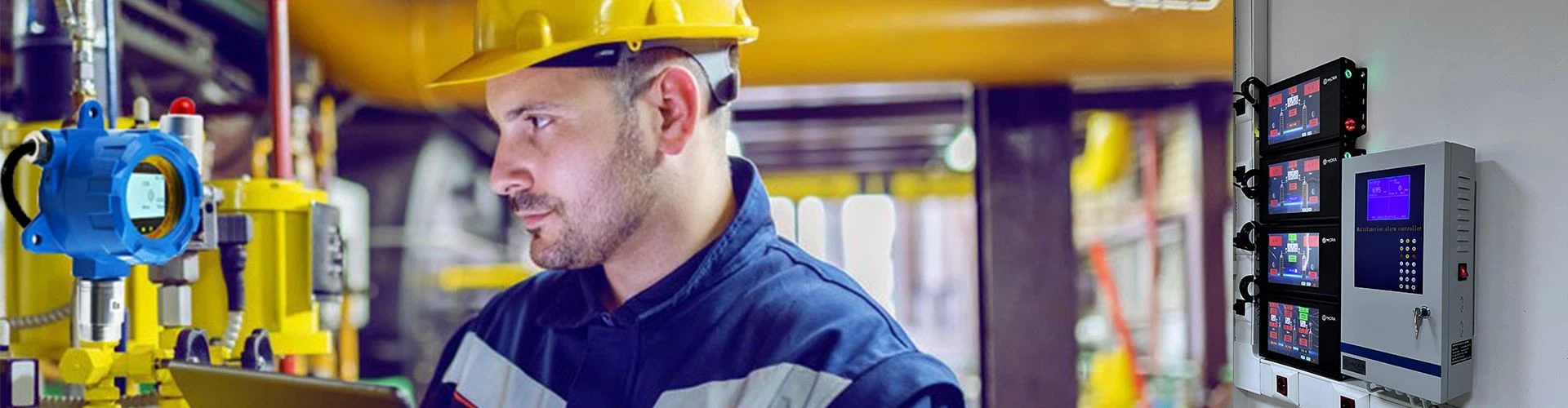
When connecting a fixed gas detector with a 4-20mA output ,also has a passive relay output (Normally open)to a fire alarm panel, analog signals (4-20mA) or switch relays need to be processed. Here is a step-by-step guide talking about how to connect gas detector to a fire alarm control panel:
1. Confirm the fixed gas detector with control panel interface
- Fixed Gas detector:
- 4-20mA output: used to continuously monitor monitor and transmit gas concentration signals.
- Passive relay: dry contact (no voltage), usually used for alarm triggering (such as high and low limit alarms).
- Fire alarm panel:
- Check whether there are analog input terminals (receive 4-20mA signals) and digital input terminals (receive relay dry contact signals).
2. Connect 4-20mA signal (analog) from fixed EX gas detector
- Wiring method:
- Connect the positive pole (+) of the detector's 4-20mA output to the positive pole (+) of the fire panel's analog input.
- Connect the 4-20mA negative pole (-) of the detector to the negative pole (-) of the analog input of the panel.
- Make sure that the analog input of the controller supports 4-20mA current signal.If the distance is far, use a shielded cable and ground it at one end to avoid interference.

3. How to connect passive relays (switch quantity) of gas detector?
- Relay usage: Usually used for gas concentration over-limit alarm (such as closing when reaching 50% of the lower explosion limit).
- Wiring method:
- Connect the COM (common end) and NO (normally open point) of the relay to the switch input terminal of the fire panel (such as "alarm input").
- The fire panel needs to provide 24V power supply (such as active input) or directly receive dry contacts (passive input):
- Active input: The panel provides 24V, and a loop is formed when the relay is closed to trigger the alarm.
- Passive input: Directly connect to the dry contact, and the panel detects on and off.
- Example wiring:
Detector relay COM → Panel alarm input terminal 1
Detector relay NO → Panel alarm input terminal 2 (or 24V+, according to panel requirements)
4. How to configure the fire alarm panel?
- Analog channel:
- Set the range (such as 0-100%LEL), corresponding to 4mA=0%, 20mA=100%.
- It may be necessary to set the alarm threshold (such as 25%LEL low alarm, 50%LEL high alarm).
- Switch channel:
- Set to normally open (NO) trigger, and activate the alarm when the relay is closed.
- Define the alarm type (such as "gas leak emergency alarm").
5. Test and verification
1. Simulate gas alarm:
- Use the calibrator to input a 4-20mA signal and check whether the panel display value matches.
- Trigger the relay (such as shorting NO and COM) to confirm the panel alarm status.
2. On-site test:
- Pass standard gas to verify the linkage alarm function.
Notes
- Explosion-proof requirements: If in a hazardous area, an explosion-proof junction box or intrinsically safe barrier must be used,and our fixed gas detector is explosion proof gas detector with CE,ATEX certificate.
- Grounding protection: Avoid signal interference and ensure that the shielding layer is grounded at a single point.
- Relay load: Confirm whether the relay capacity (such as 5A/24V) matches the panel input requirements.
Through the above steps, the LEL gas detector and the fire alarm panel can be reliably linked.
If you need LEL gas detector or EX gas detector pls contact us lucy@huafankj.com