


Commercial gas leak detectors often require lpg detectors and solenoid valves, a classic and practical gas safety linkage control system. Using a standard relay controller (often called an "alarm controller" or "gas alarm control box") instead of a PLC is perfectly feasible and the most common, low-cost, and highly reliable solution.
1.The core logic of the entire system is:
detector alarm → controller activation → relay output → solenoid valve de-energizes and closes.
Below, I will explain in detail the connection method, operating principle, and precautions.
2.System Components and Operating Principle:
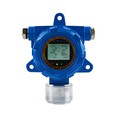
EX Gas detector: Responsible for detecting gas concentration in the air. When the concentration reaches its set alarm threshold, it sends a signal to the controller.
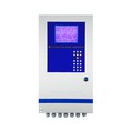
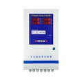
Alarm controller: The brains of the system. It receives the detector signal and controls the internal relays according to preset logic (usually immediately upon an alarm).
Solenoid valve: Installed on the gas pipeline, it serves as the final actuator. It is typically normally open (open when powered on, closed when powered off) to ensure automatic gas shutoff in the event of a power outage or emergency.
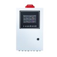
Interlocking control panel: This refers to the control box that houses the alarm controller, relays, power supply, and wiring terminals.
Principle: Under normal situation, the controller supplies power to the solenoid valve, keeping it open and supplying gas normally. If a leak occurs and the lpg detector sounds an alarm, the controller immediately cuts off power to the solenoid valve, causing the spring to quickly close, shutting off the gas.
3.Detailed Connection Steps
Step 1: Understand the Device Interfaces
Before wiring, be sure to read the manuals for all three devices and identify the corresponding wiring terminals.
LPG Gas Leak Detector:
Typically has: power supply positive and negative terminals (V+/V- or POWER) and alarm signal output (ALARM or COM/NO/NC).
The alarm output is typically a relay contact (passive dry contact) with three terminals: common (COM), normally open (NO), and normally closed (NC). COM and NO are commonly used.
4.Gas Alarm Controller:
Input Port: Used to connect the detector's alarm signal. Typically labeled INPUT or ALARM IN, it also consists of a set of COM and NO (or IN+ and IN- for active signals, but relay outputs are more common).
Output port: This is a relay inside the controller that is triggered by an alarm signal. Typically labeled OUTPUT, RELAY, or CONTROL, it also consists of three terminals: COM, NO, and NC. We use either COM and NC (normally closed) or COM and NO (normally open), depending on the logic design, as explained below.

5.Solenoid valve:
The interface is the simplest, consisting of two wires: the positive (+) power supply and the negative (-) power supply. Confirm the operating voltage (usually DC 24V or AC 220V) to match the controller's output power.
Step 2: Wiring Logic and Solution (Critical!)
Here are the two most common wiring solutions. Solution 1 is recommended because it adheres to the "fail-safe" principle.
Solution 1: Power Off to Close the Valve (Fail-Safe)
In this solution, the solenoid valve requires continuous power to remain open. In the event of an alarm or system power outage, the solenoid valve will lose power and close, providing maximum safety.
The controller output uses a "normally open (NO)" contact.
Operating Logic:
Normal State: The controller has no alarms, the internal relay is inactive, and the COM and NO terminals are disconnected. At this point, the solenoid valve is not receiving power and is closed? Incorrect! Additional "safe power-on" logic is required.
To achieve "open valve in normal operation and closed valve in alarm," we need an external power supply, independent of the controller's alarm relay, to power the solenoid valve. However, this defeats the purpose of the linkage.
Let's correct this and use a more standard connection method:
Actually, the more standard approach is to use the "normally closed (NC)" contact of the controller's output relay to create a "normal on, alarm off" circuit.
6.Correct Standard Connection Method :
First, connect the solenoid valve's operating power supply (e.g., the positive terminal of a 24V DC power supply) in series to the normally closed (NC) terminal of the controller's output relay.
Then connect the wire from the common terminal (COM) to the positive (+) terminal of the solenoid valve.
The negative (-) terminal of the solenoid valve is directly connected to the negative terminal of the power supply.
Normal State: The controller has no alarms, and the COM-NC contacts of its internal output relay are conductive. Current flows smoothly, energizing the solenoid valve and opening it.
Alarm State: When the detector alarms, the controller immediately activates the internal relay, disconnecting the COM-NC contacts. This disconnects the power supply circuit to the solenoid valve, de-energizing it and rapidly closing it.
Power Failure State: Similarly, the solenoid valve loses power and closes. (Safest)
7.Wiring Description:
LPG Detector to Controller:
Connect the detector's COM terminal to the controller's IN_COM input.
Connect the detector's NO terminal to the controller's IN_NO input.
Apply power (V+, V-) to both the detector and controller.
LPG gas alarm controller to solenoid valve:
Connect the positive terminal (V+) of the external 24V power supply to the OUT_NC (normally closed) terminal on the controller output.
Connect the OUT_COM (common) terminal on the controller output to the positive terminal (+) of the solenoid valve.
Connect the negative terminal (-) of the solenoid valve directly to the negative terminal (V-) of the 24V power supply.