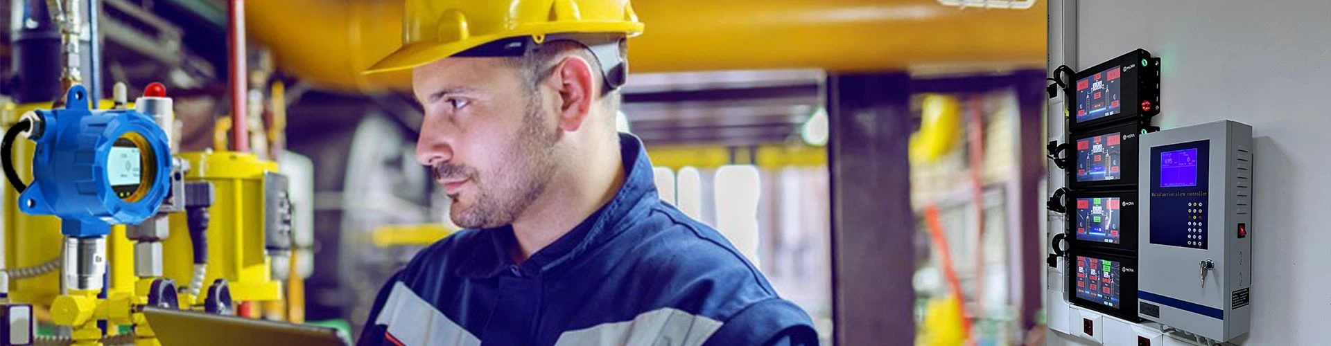


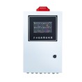

The fire alarm system comprises triggering devices-such as smoke detectors, heat detectors, flame detectors, and combustible EX gas detector-as well as a fire alarm control panel, which is used to receive and display real-time data signals, issue alarms, and transmit commands. Concurrently, it interfaces with and activates various auxiliary systems, including fire suppression systems, smoke extraction systems, fire compartmentation systems, and evacuation assistance systems.
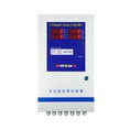
Many industrial and commercial area require the detection of combustible gas leaks; examples include commercial kitchens (LPG), LPG standard gas cylinder storage rooms, hydrogen production plants, battery rooms, and combustible gas pipelines. Typically, fixed LEL (Lower Explosive Limit) gas detectors are installed at potential leak sites. These EX detectors output real-time gas concentration data via a 4–20mA analog signal, allowing the data to be monitored on a dedicated gas control panel. When the gas concentration exceeds a specific threshold, an alarm is triggered, simultaneously activating on-site exhaust fans or solenoid valves. However, in the absence of a dedicated gas control panel, how can a combustible gas detector be directly connected to a fire alarm control panel?

Scenario 1: Relay Output (Alarm Interlock): The combustible gas detector features Normally Open (NO) contacts and a Common (COM) terminal. The detector's "Alarm/Fault" relay output terminals are connected to an input module on the fire alarm control panel. Generally, the NO and COM terminals can be wired-either directly or via an intermediate relay-to control devices such as fans or valves; alternatively, these contacts can be wired to a specific module on the control panel. When an alarm condition occurs, the NO contact closes (completing the circuit), thereby activating the exhaust fan to ventilate the area. However, this method does not allow for the retrieval of real-time gas concentration values.
Scenario 2: 4–20mA Output: The positive terminal of the EX detector's 4–20 mA signal output is connected to a signal input terminal on the fire alarm control panel, while the negative terminal is connected to the signal common ground. This method enables the transmission of real-time gas concentration data.
Wiring for Interlocked Device Control:
By utilizing the detector's Normally Open (NO) and Common (COM) terminals, devices such as fans or valves can be connected directly or via an intermediate relay. For instance, during an alarm event, the NO contact closes to activate the exhaust fan for ventilation. Explosion-Proof Requirements: When installing equipment in hazardous areas, all cabling must be routed through conduit and properly sealed using explosion-proof sealing techniques. The fire alarm control cabinet is equipped with corresponding input modules; the relay outputs from the LEL gas detectors are connected to the input terminals of these modules, which then communicate with the fire control panel via the SLC (Signal Loop) .