




1.Preparations before installation:
Verify device information: Before installation, be sure to confirm that all devices have unique Modbus addresses, consistent serial port parameters (baud rate, data bits, parity bits, stop bits), and prepare the corresponding register mapping table.
Planning and Labeling: Plan the layout within the cabinet, reserving space for future expansion. Before pulling in each cable, clearly label the cable as A/B/+24V, GND , and prepare a clear wiring diagram and address table.
2.Electrical connections:
Power supply: Confirm the power supply voltage of the detector (e.g., 12 ~ 36V DC ; the rated operating voltage of a gas detector is usually 24V DC, and the operating voltage of the control cabinet is 110-240V ) to ensure that the power supply is sufficient and stable.
RS485 communication cable: Note that the A/B wires must not be reversed. Use shielded twisted-pair cable, with a recommended wire gauge of 1 to 1.5 square millimeters .
3.Key points for connection:
Strong and weak current separation: Strong current (AC 220/380V) and weak current (DC 24V, signal line) must be routed separately, or the gas detector should be connected to the 24V output voltage on the gas control cabinet.
Cable management: Use wire number tubes to identify each wire.
3.Power supply and grounding:
Power supply: Reserve more than 30% power margin for DC 24V power supply.
Grounding: The RS485 shielding layer should be grounded at one end to avoid ground loop current caused by multiple grounding points.
4.RS485 Modbus Communication Network Installation Guidelines
Bus topology (daisy-chain): A daisy-chain bus topology must be used . Star connections are strictly prohibited .
Cable selection and wiring: Dedicated RS-485 shielded twisted-pair cable must be used. Communication lines should be kept away from high-voltage power cables and high-interference sources such as frequency converters.
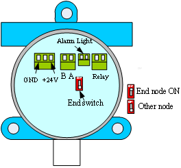
Termination resistor: When the bus length exceeds 30 meters or the communication rate is high, a 120Ω termination resistor must be connected in parallel at both ends of the bus (the master station and the last device). Our gas detector has an integrated 120Ω bias resistor , which can be selected by a switch .
Grounding and Shielding: The signal grounds (GND) of all devices should be interconnected using shielded twisted-pair cable, with the shield grounded at only one end . The following points should be noted :
(1) It is recommended to use two separate wires for power and signal. The signal wire must be shielded twisted pair as shown in Figure 1. Using shielded twisted pair helps reduce and eliminate distributed capacitance between the two 485 communication lines and common-mode interference from the surrounding area of the communication lines. The power wire should be shielded as shown in Figure 2. The 485 transmission distance varies depending on the selected wire and generally will not reach the theoretical maximum transmission distance of 1000M .

Figure 1 Signal line twisted pair shielded wire

Figure 2 Power cord shielding wire
We recommend using RVVP2×32/0.2 (2×1.00) or RVVP2×48/0.2 (2×1.50).
(2) During construction, the transmission wire should avoid loops as much as possible, that is, forming a loop coil with multiple turns at a certain point.
(3) During construction, the pipe should be run separately and kept away from high-voltage power lines as much as possible to avoid being near strong electric or magnetic field signals.
(4) The 485 bus must adopt a daisy-chain structure, and star connections and branch connections must be strictly avoided . Star connections and branch connections will generate reflected signals, thus affecting 485 communication. The length of the branch lines from the main bus line to each terminal device should be as short as possible, generally not exceeding 5 meters. The shielding layer is connected to the transmitter 's housing . That is, it is only connected to ground at the control panel end, while at the field detector (slave station) end, the shielding layer is only connected to the metal housing of the detector .
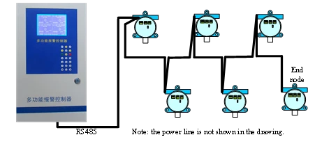
5) After the wiring is completed, connect a portion of the transmitters first, disconnect the power and signal lines at the rear end, and terminate the transmitters at the end of the connection . Use a multimeter to test whether there is a short circuit between the signal and power lines. The resistance between signal lines A and B should be approximately 50-70 ohms. Check if the host can communicate, and then connect another portion for testing. Only terminate the transmitters at the end of the bus; other transmitters should not be terminated.
(6) When too many gas detectors are connected and the distance is too far, the following fault phenomena will occur.
a. If all nodes fail to receive data and the indicator lights inside the transmitter are off, it means the power supply cannot provide enough current. You need to connect another switching power supply. It is recommended to use a high-power power supply. The power supply of the new switching power supply needs to be disconnected from the power supply of other switching power supplies at some point.
b. If severe node loss occurs, it is due to excessive communication distance and unstable bus data, requiring the addition of repeaters to extend the communication distance.
5.Debugging and Acceptance:
Pre-power-on checks: Use a multimeter to check for short circuits in the power supply and communication lines.
Parameter verification: After powering on, reconfirm that the addresses and communication parameters of all devices are consistent with the plan.
Communication testing: Connect to a single device to test communication, and add more devices one by one after successful connection, rather than connecting all devices at once.